


From Wiki:
Cylinder head porting refers to the process of modifying the intake and exhaust ports of an internal combustion engine to improve the quality and quantity of the gas flow. Cylinder heads, as manufactured, are usually suboptimal due to design and manufacturing constraints. Porting the heads provides the finely detailed attention required to bring the engine to the highest level of efficiency. More than any other single factor, the porting process is responsible for the high power output of modern engines.
This process can be applied to a standard racing engine to optimize its power output as well as to a production engine to turn it into a racing engine, to enhance its power output for daily use or to alter its power output characteristics to suit a particular application.
Daily human experience with air gives the impression that air is light and nearly non-existent as we move slowly through it. However, an engine running at high speed experiences a totally different substance. In that context, air can be thought of as thick, sticky, elastic, gooey and heavy (see viscosity). Pumping it is a major problem for engines running at speed so head porting helps to alleviate this.
Port modifications
When a modification is decided upon through careful flow testing with an air flow bench, the ports are carefully reshaped with die grinders. Sometimes the ports must be welded up or similarly built up to add material where none existed.
This illustration shows the difference between a poor performing port and an excellent design after porting modification. The difference between the two show the general idea of improving port flow. Higher and straighter is better for peak power.
The modification shown is commonly referred to "increasing the downdraft angle", and is limited by mechanical constraints such as engine bay height, the amount of material in the parent casting, or the relocation of valve gear to accommodate the longer valve stem.
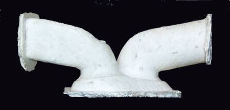
Shown here is a mold of the ports of a Ford two liter head destined for use in Formula 2000 racing. It is shown as manufactured with the intake port on the right and is badly in need of porting to alleviate the flow restrictions. -(Interestingly, this head received extensive flow bench development by Ford at design time but because of engine height restrictions, the use of cast iron and lack of knowledge at the time, this was the best that could be manufactured. Today, manufacturers are able to do much better although they still cannot approach the quality of hand porting.)
The Ford two liter shown above in stock trim is capable of delivering 115 horsepower@5500RPM for a BMEP of 140psi. Contrast this with the Pro Stock ports shown below.
This GM Pro Stock head is capable of 1300 horsepower@8500RPM with a BMEP of 238psi. Since BMEP is an excellent efficiency measure and closely related to volumetric efficiency, the Pro Stock head is vastly better than the Ford. In fact a BMEP of 238 puts it at the top of the racing engine world. It is close to the limit for naturally aspirated gas burning engines.
Of course cam characteristics and other things play a role in this difference as well but the difference in port design is a major factor.
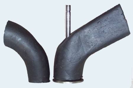
This photo is of port molds of a highly developed 500 cubic inch GM Pro Stock head. Note the height and straightness of the ports, particularly the exhaust port on the left. -(This design is based on a cylinder head casting, which is purpose-built just for Pro Stock applications. The head is supplied with small ports with plenty of material everywhere for individual porting specialists to shape to their requirements without welding.)
Parts of the port and their terminology
Areas of importance
Considering the flow through the intake port as a whole, the greatest loss must be downstream of the valve due to the lack of pressure recovery (or diffusion). This loss is unavoidable on intake ports due to the nature of the poppet valve. On the exhaust ports the opposite condition exists and we are able to control the geometry down stream of the highest speed section, namely the valve seat. This allows the possibility of good pressure recovery and is the reason exhaust ports flow better than intake ports of equal size.
Accepting the expansion into the cylinder loss as unavoidable, the rest of the port becomes that much more important. The areas which pass the most air at the highest speed for the longest time are the areas that are most important.
The valve seat configuration on the port and on the valve together form one of the most critical areas in the port. The highest speed seen in the port will be at or near the valve seat for most if not the entire duration of the cycle. After that the throat area and short turn radius become critical at higher lifts in the middle of the cycle. The valve seat and valve head angles should be studied carefully in each design.
The bowl area and the rest of the length of the port have important functions in controlling some of the dynamic behavior of the waves that traverse the system as well as setting up the air for a good entry to the throat. Shape, cross section, volume, cylinder swirl or tumble and surface finish are factors which must be considered in concert with the overall design of the rest of the engine and vehicle to achieve good results.
The port is shaped to allow the maximum use of the available cross sectional area. Port flow velocity should be optimized for the conditions the engine is expected to see. Well shaped ports will have few dead spots.
Wave Dynamics
This highly simplified animation shows how air flows as waves in an intake system. Note the green "valve" opening and closing.
When the valve opens, the air doesn’t flow in, it decompresses into the low-pressure region. All the air on the upstream side of the moving disturbance boundary is completely isolated and unaffected by what happens on the downstream side of it. The air at the runner entrance does not move until the wave reaches all the way to the end. It is only then that the entire runner can begin to flow. Up until that point all that can happen is the higher pressure gas filling the volume of the runner decompresses or expands into the low-pressure region advancing up the runner. (Once the low pressure wave reaches the open end of the runner it reverses sign, the inrushing air forces a high pressure wave down the runner. Not shown in this animation.)
Conversely the closing of the valve does not immediately stop flow at the runner entrance, which continues completely unaffected until the signal that the valve has closed reaches it. The closing valve causes a buildup of pressure which will travel up the runner as a positive wave. The runner entrance continues to flow at full speed, forcing the pressure to rise until the signal reaches the entrance. This very considerable pressure rise can be seen on the graph below. At the closing of the intake valve, pressure rises far above atmospheric.
It is this phenomenon that enables the so-called “ram tuning” to occur and it is what is being “tuned” by tuned intake and exhaust systems. The principle is the same as in the water hammer effect so well known to plumbers. The speed that the signal can travel is the speed of sound in the gas inside the runner. The boundary between the wave affected gas and unaffected gas could be compared to the event horizon of a black hole.
This is why port/runner volumes are so important; the volumes of successive parts of the port/runner control the flow during all transient periods. That is, any time a change occurs in the cylinder - whether positive or negative - such as when the piston reaches maximum speed.
This point always occurs where the crank throw or journal is at right angles to the connecting rod beam, and will vary somewhat with the connecting rod ratio (rod / stroke). For normal automotive design this point is almost always between 69 and 79 degrees ATDC, with higher rod ratios favoring the later position. It will only occur at 1/2 stroke (90 degrees) with a connecting rod of infinite length.
The wave/flow activity in a real engine is vastly more complex than this but the principle is the same.
At first glance this wave travel might seem to be blindingly fast and not very significant but a few calculations shows the opposite is true. In an intake runner at room temperature the sonic speed is about 1100 feet per second and will traverse a 12 inch port/runner in 0.9 milliseconds. The engine using this system, running at 8500 RPM, takes a very considerable 46 crank degrees before any signal from the cylinder can reach the runner end. 46 degrees during which nothing but the volume of the port/runner supplies the demands of the cylinder. This not only applies to the initial signal but to any and every change in the pressure or vacuum developed in the cylinder.
Why couldn’t we just use a shorter runner so the delay is not so great? The answer lies at the end of the cycle when that big long runner now continues to flow at full speed disregarding the rising pressure in the cylinder and providing pressure to the cylinder when it is needed most. The runner length also controls the timing of the returning waves and cannot be altered. A shorter runner would flow earlier but also would die earlier while returning the positive waves much too quickly and those waves would be weaker. The key is to find the optimum balance of all the factors for the engine requirements.
Further complicating the system is the fact that the piston dome, which is the source of the signal, continually moves. First moving down the cylinder, thus increasing the distance the signal must travel. Then moving back up at the end of the intake cycle when the valve is still open past BDC. The signals coming from the piston dome, after the initial runner flow has been established, must fight upstream against whatever velocity has been developed at that instant, further delaying the signal. The signals developed by the piston do not have a clean path up the runner either. Large portions of it will bounce off the rest of the combustion chamber and resonate inside the cylinder until an average pressure is reached. Then there are temperature variations due to the changing pressures and absorption from hot engine parts. These variations cause changes in the local sonic velocity.
When the valve closes, it causes a pile up of gas giving rise to a strong positive wave which must travel up the runner. The wave activity in the port/runner does not stop but continues to reverberate for some time. When the valve next opens, the remaining waves influence the next cycle.
This graph shows the pressure taken from the valve end (blue line) and the runner entrance(red line) of an engine with a 7inch port/runner and running at 4500 RPM. Highlighted are two waves, suction wave and valve closing wave, seen and the valve end and runner entrance showing the signal delay.
The graph above shows the intake runner pressure over 720 crank degrees of an engine with a 7-inch intake port/runner running at 4500 RPM, which is its torque peak (close to maximum cylinder filling and BMEP for this engine). The two pressure traces are taken from the valve end (blue) and the runner entrance (red). The blue line rises sharply as the intake valve closes and this causes a pile up of air which becomes a positive wave reflected back up the runner and the red line shows that wave arriving at the runner entrance later. Note how the suction wave during cylinder filling is delayed even more by having to fight upstream against the inrushing air and the fact that the piston is further down the bore, increasing the distance.
The goal of tuning is to arrange the runners and valve timing so that there is a high-pressure wave in the port during the opening of the intake valve to get flow going quickly and then to have a second high pressure wave arrive just before valve closing in order to fill the cylinder as much as possible. The first wave will be what is left in the runner from the previous cycle while the second will primarily be one created during the current cycle by the suction wave changing sign at the runner entrance and arriving back at the valve in time for valve closing. The factors involved are often contradictory and requires a careful balancing act to work. When it does work, it is possible to see volumetric efficiencies of 140%, similar to that of a decent supercharger, but it will only occur over a limited RPM range.
The "Porting and Polishing" Myth
It is popularly held that enlarging the ports to the maximum possible size and applying a mirror finish is what porting is. However that is not so. Some ports may be enlarged to their maximum possible size (in keeping with the highest level of aerodynamic efficiency) but those engines are highly developed very high speed units where the actual size of the ports has become a restriction. Often the size of the port is reduced to increase power. A mirror finish of the port does not provide the increase that intuition would suggest. In fact, within intake systems, the surface is usually deliberately textured to a degree of uniform roughness to encourage fuel deposited on the port walls to evaporate quickly. A rough surface on selected areas of the port may also alter flow by energizing the boundary layer, which can alter the flow path noticeably, possibly increasing flow. This is similar to what the dimples on a golf ball do. Flow bench testing shows that the difference between a mirror finished port and a rough textured port is typically less than 1%. The difference between a smooth to the touch port and an optically mirrored surface is not measurable by ordinary means. Exhaust ports may be smooth finished because of the dry gas flow but an optical finish is wasted effort and money.
The reason that polished ports are not advantageous from a flow standpoint is that at the interface between the metal wall and the air, the air speed is ZERO (see boundary layer and laminar flow). This is due to the wetting action of the air and indeed all fluids. The first layer of molecules adheres to the wall and does not move significantly. The rest of the flow field must shear past which develops a velocity profile (or gradient) across the duct. In order for surface roughness to impact flow appreciably, the high spots must be high enough to protrude into the faster moving air toward the center. Only a very rough surface does this.
A developed velocity profile in a duct that shows why polished surfaces have little effect on flow. The air speed at the wall interface is zero regardless of how smooth it is.
Methods
The die grinder is the stock in trade of the head porter. They are used with a variety of carbide cutters, grinding wheels and abrasive cartridges. The complex and sensitive shapes required in porting necessitate a good degree of artistic skill with a hand tool.
Until recently, CNC machining was used only to provide the basic shape of the port but hand finishing was usually still required because some areas of the port were not accessible to a CNC tool. New developments in CNC machining now allow this process to be fully automated with the assistance of CAD/CAM software. 5-Axis CNC controls using specialized fixtures like tilting rotary tables allow the cutting tool full access to the entire port. The combination of CNC and CAM software give the porter full control over the port shape and surface finish.
Measurement of the interior of the ports is difficult but must be done accurately. Sheet metal templates are made up, taking the shape from an experimental port, for both cross-sectional and lengthwise shape. Inserted in the port these templates are then used as a guide for shaping the final port. Even a slight error might cause a loss in flow so measurement must be as accurate as possible. Confirmation of the final port shape and automated replication of the port is now done using digitizing. Digitizing is where a probe scans the entire shape of the port collecting data that can then be used by CNC machine tools and CAD/CAM software programs to model and cut the desired port shape. This replication process usually produces ports that flow within 1% of each other. This kind of accuracy, repeatability, time has never before been possible. What used to take 18hrs. or more now takes less than 3hrs.
Valves and valve seats are ground with special equipment designed for this purpose.
Summary
The internal aerodynamics involved in porting is counterintuitive and complex and absolutely requires an air flow bench, a thorough knowledge of the principles involved and use of engine simulation software in order to determine what needs to be done to optimize a port.
Although a large portion of porting knowledge has been accumulated by individuals using "cut and try" methods over time, the tools and knowledge now exists to develop a porting design with a measure of certainty. Porting by inexperienced individuals without a full understanding of the fluid dynamics of the process still continues but the results are spotty and the process is expensive and time consuming with many more failures than successes.
Hope the info helps.


